Week 1
Nuke 3d and Camera Projection
This week's lesson started with an introduction to 3D view in NukeX and how it affects the camera projection.
We started of by bringing a camera and two 3D objects connected them with a color bar and checker board.
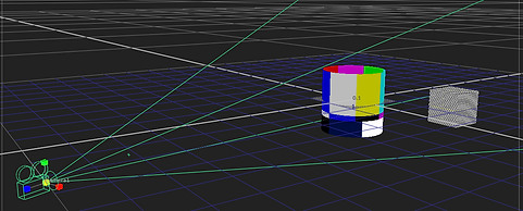
3D and 2D point of view in NukeX of 3D shapes with texture


This is a basic elements of a 3D scene node graph in NukeX example.
From top to bottom we have:
-
Texture (ColorBars & CheckerBoard)
-
Geomtery (Cylinder and cube)
-
Scene (Acts as a 'merge' node in 3D space)
-
Camera (Without it there is no 2D view option of the scene)
-
Scanline Render (converts 3D back to 2D)
Exercise 1
The first exercise was to create an image sequence from a single image and create an illusion as if the camera is going through the tunnel.
To achieve such a result we learnt two methods and both are 3D scenes.

The original tunnel image
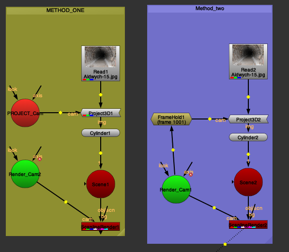
Method one:
-
In 3D view I added a cylinder and connected with the image.
-
We had a pre-done set render camera, so for the first method we had to duplicate the render camera, rename it to project camera and delete any animation from it and connect the to project3D node.
-
Scanline render connected via obj pipe to scene node and render camera connected via cam pipe.
Method two:
-
Instead of duplicating the render camera and removing it's animation we jus made a framehold of the first frame and achieved same result.
Final result
Exercise 2
The second exercise was to create a 3D prison cell out of an image and make a sequence of camera going through the bars into the prison cell.
The main difference from the previous exercise is that we had to create several cards for different angle's (left wall, right wall, roof, back wall, flooring) rather than one cylinder, it would't work in this case at all.

Prison cell image

Prison bars
Node graph


The method to create a 3D environment out of a picture is to roto out and premult every single wall, roof and flooring one by one on each different 3D card shape, Project3D connect to projection camera, scanline render to render camera. Merge.
Final result
Week 2
Nuke 3D Tracking
This week's class was about tracking options in using NukeX 3D environment as well as fixing lens distortion.

Distortion occurs when a lens produces curved lines where straight lines should take place. A perfect lens would maintain all lines straight.
Most lenses aren't perfect and bend lines outwards or inwards from the center of the image.
Distortion occurs more commonly in zoom lenses and can vary as the focal length changes.
Fixing lens distortion is important as human eye and brain can easily recognise distortion, even subtle one.
Example of lens distortion before and after
To correct lens distortion in Nuke we use ST Maps as an example on the right and reformat node

Node graph
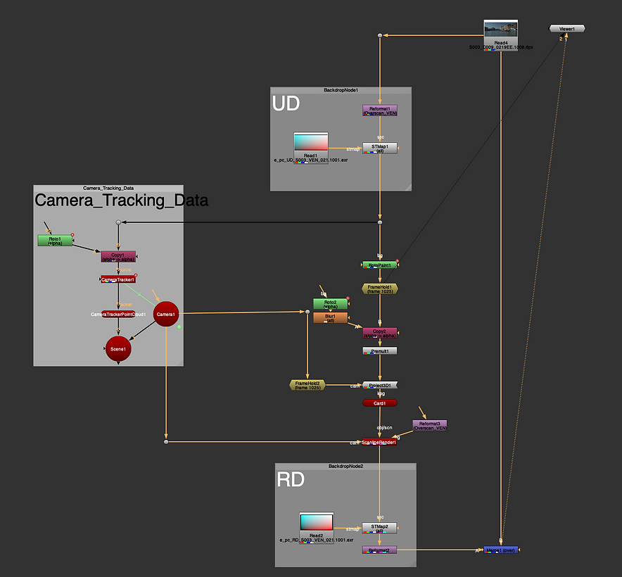
Here above is the full node graph of this week's lesson. The UD and RD nodes are the lens distortion nodes.
After lens distortion correction we learnt how to Roto objects from the scene while using Camera trackers.

So our task was to remove 2 windows from a building and create a blank wall.
After creating a camera tracker the first step was to project a 3D card object into our scene with a checker board. After that we removed the checkerboard and replaced it with a framehold of roto painted out windows out of the scene.
Now the card held the information of blank wall with no windows that we just painted. Scanline render connected with the object card and camera and that's it.
Elements of 3D scene
Help sheet

Before footage
After footage
Week 4
3DE Freeflow and Nuke
We started using a new software which is called 3DEqualizer. It's a 3D tracking solution software and in this week's lesson we learnt how to set up our project in 3DE, set shortcuts on keyboard, how to import image sequence and gauge and track.
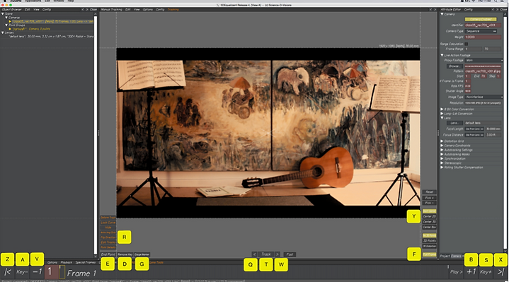
3DEqualizer shortcuts

3D orientation view in 3DE. Here we can see the yellow dots, they are trackers made in different places of the footage as well as camera itself and it's movement (red line)
Below we added locators to have a clearer view of the trackers and adjusted their size.


Here are the trackers and a 3d object placed into the render sequence in the lineup view in 3DE.
Next step is baking and exporting files and fbx locators and 3d model and go to Nuke.

After importing everything to Nuke it was time to fut the Geo objects (3d model and locators) into the original render sequence, add lens distortion node from 3DE.

All important files form 3DE as well as the original sequence

Node graph of the imported files from 3de added to the render sequence
To see geo locators we used a constant node and coloraturas of choice and wireframe node (see through) for the 3d cylinder to appear as clear wired object.
Lens distortion node right before the merge

Assignment 1
Part 1
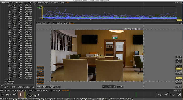
Tracking in 3DE
After importing the footage I adjusted the camera settings according to the survey data image

Next step was to track as many points as possible and try to make them as accurate and solid as possible

I had over 45 trackers, later on I saw that a few of them are not tracking properly, therefore, I either removed them from the scene or remove and replaced with a more accurate tracker


3D orientation view of my trackers, the score at this point was 0.3896 which is below 1, there quite accurate
Later on the number dropped a little bit more, since I did a few adjustments

Adjusting parameters is a great way to make your number lower.
Shortcut to open Parameter Adjustment is Alt+6
Adjust desired parameter, brute force all and transfer parameters
After press Alt+C and calculate the adjustments.
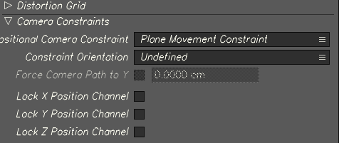
I choose Plane movement camera control to get a lower overall Deviation browser score
Part 2
Distance constraint

The survey data image
Below were the camera parameters and for my distance constraint I chose the counter which was 1.4m long

To create a constraint, open up 3D orientation view, select two trackers that you want to create a distance between them and create a distance constraint
This is my distance constraint in 3D orientation view

Part 3
Aligning scene, Locators and Geo object
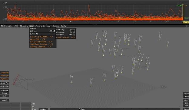
I created locators by selecting all of my trackers, navigate to 3d orientation > Geo > Create > Locators
Then I made them slightly larger by using 'Scale up Locators' option in same option window.
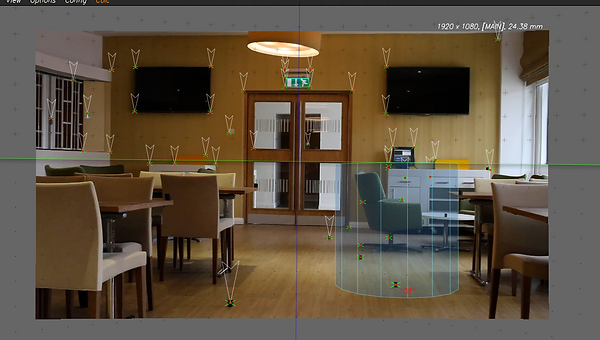
Geo locators in the scene


To create a 3D Cylinder I choose one of the trackers and navigated to 3D orientation > 3D Models >
Create > Cylinder
Snapped it to the point
My cylinder was quite massive, therefore, I scaled him down a little
The next step was to bake the scene and export all the files

Part 4
Nuke
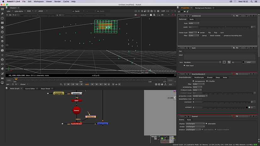
The point cloud from 3DE in Nuke 3d view

Started off by organising all the imported data from 3DE, the lens distortion node, Geo nodes and camera data
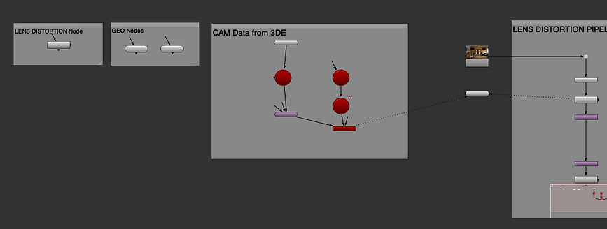
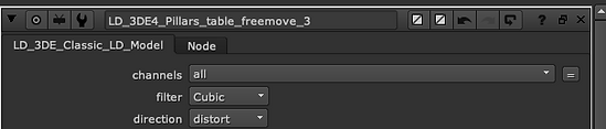
To make the LD work I chose the direction from undistort to distort
The Node graph to make locators, cylinder and lens distortion appear in render sequence

Once that was done I had another task of removing the exit sign above the doors
Node graph showing the process of removing the exit sign

The final outcome
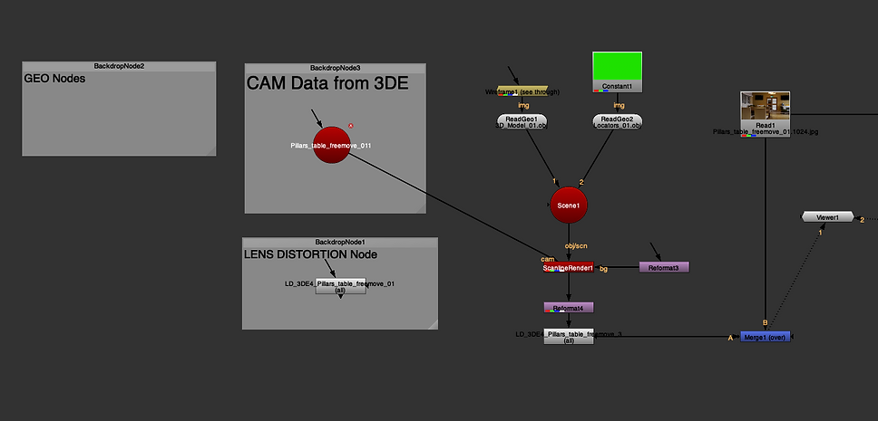
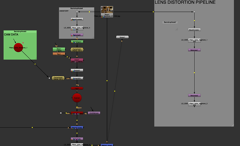
Node graph for this assessment

The left half of the Node graph
It mainly shows the progress of the cylinder and locators put into the scene and redistortion (it's disabled since it comes up again later in the pipeline)

The right half of Node graph showing the removal of the exit sign, lens undistortion to remove the exit sign and later on distortion, right before merge
Final result


Preparation for assignment 2
For our second assignment we got a Maya file with a render sequence and 3d point cloud.
My task is to model three 3d objects or characters, texture them, rig and animate if possible and place into the given scene.

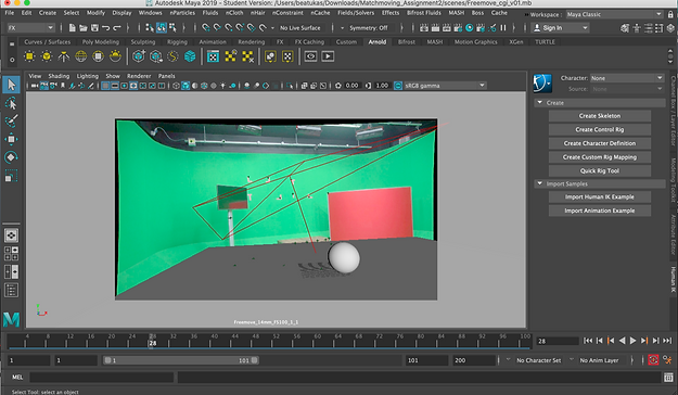
Render view of the given set

Here I tried to put in a 3d model from my previous assignment, just to see and have a look how does it work
First 3d Model
For my first model I decided to play a little bith with the FX in Maya and to do a ghost like cloth hanging around the scene.
First off I created a plane, added more subdivisions into it, selected the place and created an nCloth.

Next step, I selected a few vertexes on the place in the middle so that they would remain in the same spot and others would move around as the wind blows.
After selecting the vertexes I created a transform constraint
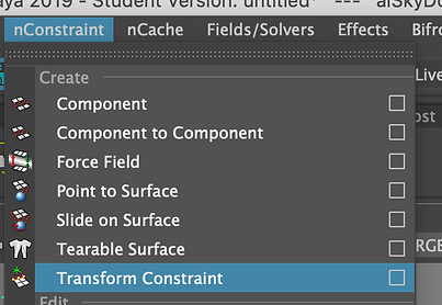


Next I cut the simulation's beginning since it was falling from a plane to a cloth
by selecting the frame that I want the simulation to start with and going to Fields/Solvers > Initial state > Set for selected
Then in Constraint shape settings I added Dropoff Distance just to the constraint vertexes wouldn't look harsh
I added Arnold Standard surface material to the cloth, choose a purple colour and velvet asset.
This is a playblast and a rendered image of the cloth that I have created. Next step was to import this mesh to the given Maya scene


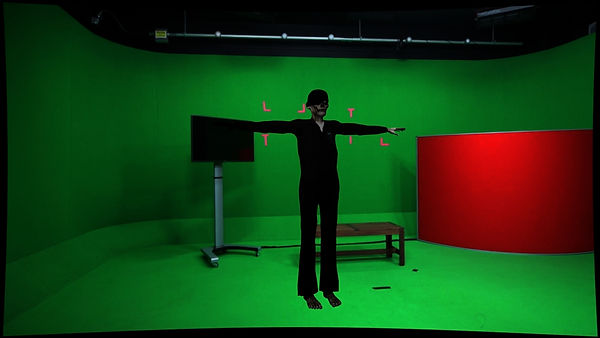
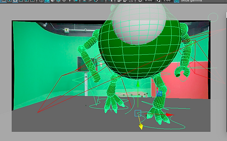
Here is the camera view in Maya after importing the mesh, for now I left the plane and light. Before rendering the sequence I will have to adjust the light settings and plane for the shadow


I decided to change to colour of sloth to white to give it more of a ghost look.
Adjusted lights and plane for the shadows

Here are perspective views in Maya before rendering, I have put three lights from different angles

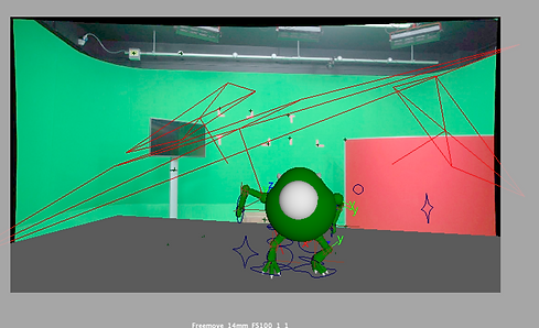
Still render of final result in Maya


Next step was to import render sequence into After Effects.
After importing I adjusted the colours, contrast and brightness.


Next thing I did was added a Adjustment Layer and added Optics compensation to remove lens distortion by adjusting Field of View (FOV)
Final render of the first 3D model
2nd Model
For my second model I decided to use Mike Wazovski that I modelled, rigged and animated in the first semester.
When I imported the model into the scene it was very very tiny so I decided to go back and scale it up and import again. Then it was to big. Shortly with a locator I managed to scale him down.
Also, here is an example of his texture before. He was very shiny
"glass" like and I changed that to more plastic/clay/ type of texture.


I used the standard Arnold surface material and used one of the presets to achieve the final colour.


After making his texture less shiny and more realistic to fit the scene and making sure his shadows are right and seen in the renders I rendered the render sequence.

Put the render sequence into After Effects and removed the lens distortion as with the previous model
Final render
Model 3

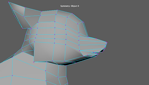
For my third model I decided to create a little wolf, found some great reference pictures and set them up accordingly. This wolf will be for the Rigging module as well.
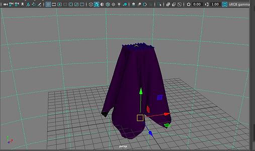
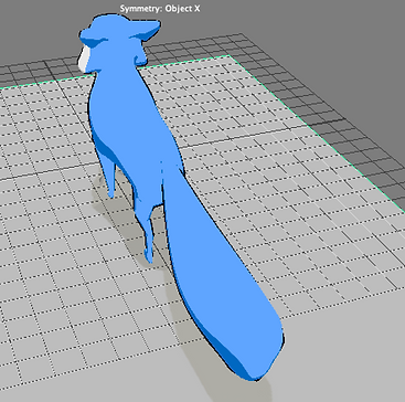
I started off by adding a cube, some divisions and started to more vertexes around into a base shape

Here is the process so far, mostly what I do is move the vertexes, extrude faces and adding edge loops to have more vertexes.
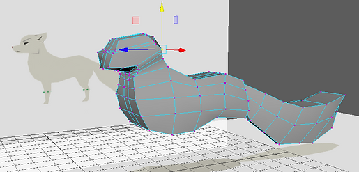
Modeling progress


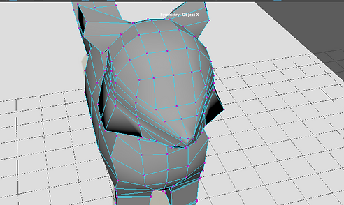
When I began modeling the face I realised that my model is somehow unsymmetrical. Therefore, I deleted it's head, fixed the body, adjusted the vertex and somehow managed to make it symmetrical. Then I did the head again.


I did the head by doing a separate cube, adding subdivisions, moving the vertex a bit and then using smooth I made it more round.
Next, I deleted some faces and snapped them with merge to the wolf's neck and combined the two into one model and continued to work on the head moving the vertex, adding edge loops and etc.


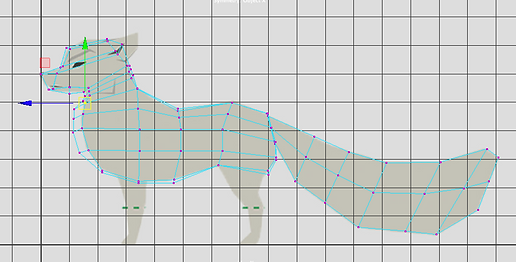
Here is the vertex according to the reference image of the side view
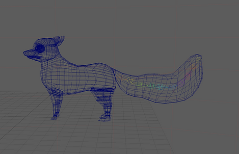
More modeling progress


Modeling progress on the face


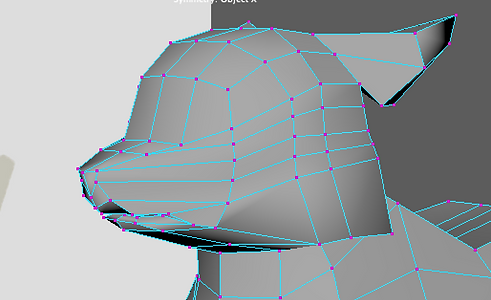
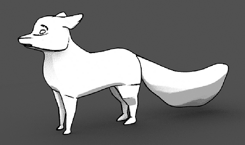
I've narrowed the mouth and still need to work on the eyes. After that I will move on to texturing, probably will do the Xgen Fur in Maya. Also will rig and animate and put it into the scene.
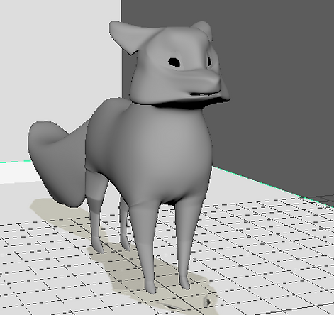
Finished model


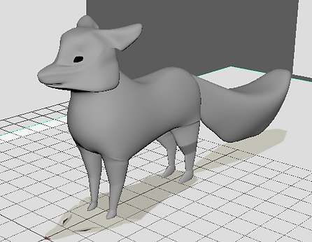
I did smooth out my model, made the mouth and the whole face more narrow, also made the eyes.
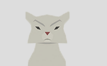
Toon Material


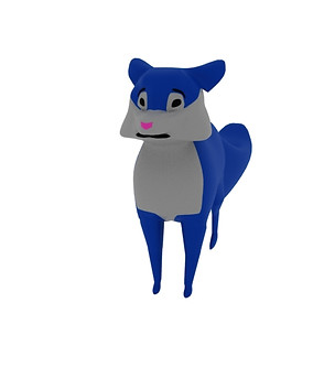
I added toon materials as well as outliner, however, this wasn't a Arnold shader, therefore, it wasn't showing in the Arnold renderer only in Maya Render. Had to redo it with AiToon shader all over again.

This is how it rendered through Maya rendered but I redid it with Arnold shaders just because I didn't know how it would render in the given scene.
Arnold AiToon material


Started by applying AiToon on all model, in render settings changed filter type to Contour and played around with Base setting, added a Tonemap Ramp where I added 2-3 colours so that depending on the shadows it would show a lighter or darker colour.


The Ramp really helped with giving definition for my model.
Rigging and animating
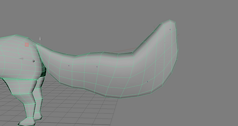
Added joints to the tail, bind them just with the faces of the tail.
Grouped them and for smoother animation I did a ikHandle and 4 cluster handles

Playblast of the animation, I just moved and keyed the clusters to achieve this